

How Can We Calculate The Duct Size

How to pattern a duct organisation. In this article we'll be learning how to size and design a ductwork system for efficiency. We'll include a full worked instance as well equally using CFD simulations to optimise the operation and efficiency using SimScale. Gyre to the bottom to spotter the FREE YouTube video tutorial!
🏆🏆🏆 Create a costless SimScale business relationship to test the deject-based CFD simulation platform hither: https://www.simscale.com/ With 100,000+ users worldwide, SimScale is a revolutionary deject-based CAE platform that gives instant access to CFD and FEA simulation technology for quick and easy virtual testing, comparison and optimization of designs in several industries, including HVAC, AEC, and electronics.
- Notice more than 50 free on-need webinars on different topics, from ventilation or data eye blueprint and wind load analysis to aerospace, F1, and sports aerodynamics here: https://www.simscale.com/webinars-wor…
- Read more about the benefits of using cloud-based engineering simulation and the SimScale Community here: https://world wide web.simscale.com/product/pricing
- Find thousands of fix-to-utilize simulation templates created by SimScale's users which you tin can copy and change for your ain analysis: https://www.simscale.com/projects/
Methods of ductwork design
In that location are many unlike methods used to design ventilation systems, the most common means being:
- Velocity reduction method: (Residential or pocket-size commercial installations)
- Equal friction method: (Medium to large sized commercial installations)
- Static regain: Very large installations (concert halls, airports and industrial)
Nosotros're going to focus on the equal friction method in this example equally information technology'due south the virtually common method used for commercial HVAC systems and its adequately simple to follow.
Design case
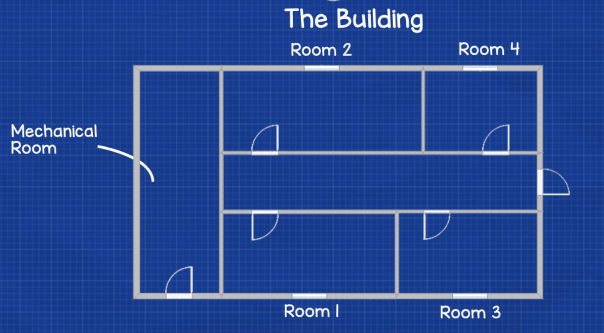
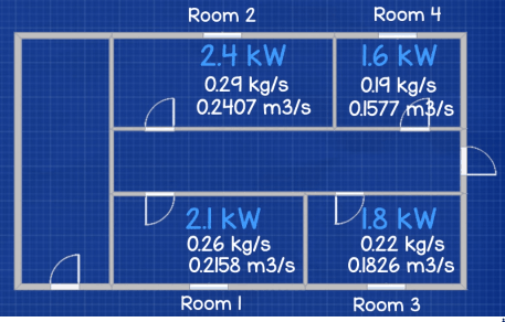
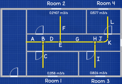
So we'll jump straight into designing a system. We'll utilize a small-scale applied science office as an example and we want to make a layout cartoon of the edifice which we'll use for the design and calculations. This is a actually simple building it has simply 4 offices a corridor and a mechanical room which is where the fan, filters and air heater or cooler will exist located.
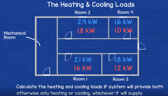
The offset matter we need to do is calculate the heating and cooling loads for each room. I won't cover how to do that in this article we'll take to cover that in a split up tutorial as it's a carve up discipline area.
Once you have these, just tally them together to find which is the biggest Load as we need to size the system to be able to operate at the peak demand. The cooling load is usually the highest, as it is in this case.
Now we demand to convert the cooling loads into volume flow rates but to exercise that we first need to convert this to mass catamenia rate then we utilize the formula:
mdot = Q / (cp x Δt)
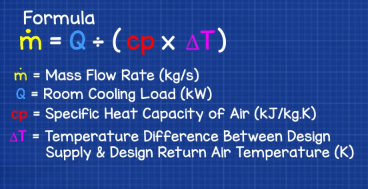
Where mdot means mass flow charge per unit (kg/southward), the Q existence the cooling load of the room (kW), cp is the specific estrus chapters of the air (kJ/kg.K) and Δt being the temperature difference between the designed air temperature and the pattern return temperature. Just to notation that nosotros will use a cp of 1.026 kJ/kg.k as standard and the delta T should be less than 10*C and so nosotros'll use 8*c.
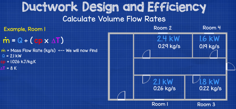
We know all the values for this so we tin can summate the mass menstruum rate (how many kilograms per second of air needs to enter the room). If nosotros await at the calculation for room 1, we see it requires 0.26 kg/s. And then nosotros just repeat that calculation for the rest of the room to find all the mass period rates.
Now we can convert these into volume menses rates. To do that we need the specific volume or density of the air. We'll specify 21*c and assume atmospheric pressure of 101.325 kPa. We can look this upward in our air properties tables merely I like to just use an online calculator http://scrap.ly/2tyT8yp every bit its quicker. So we just drop those numbers in and nosotros get the density of air being 1.2 kg/m3.
You run into that density has the units of kg/m3 but we need specific volume which is m3/kg so to convert that we but take the changed which means to calculate 1.2 to the power of -1. You tin can just practise that in excel very rapidly (re-create paste this =1.2^-i) to get the answer of 0.83m3/kg.
Now that we take that we tin can calculate the volume menses charge per unit using the formula:
vdot = mdot multiplied by five.
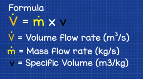
where vdot equals the volume menses rate, mdot equals the mass catamenia rate of the room and 5 equals the specific volume which we just calculated.
And then if we drib those values in for room 1 we get a book flow rate of 0.2158m3/s that is how much air needs to enter the room to meet the cooling load. So but repeat that calculation for all the rooms.
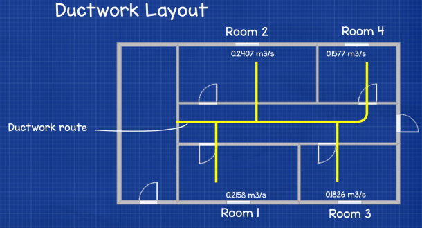
Now we're going to sketch out our ductwork route onto the floor plan and so we tin kickoff to size it.
Before we become any further we demand to consider some things which will play a big role in the overall efficiency of the arrangement.
Design considerations
The first one being the shape of the ductwork. Ductwork comes in round, rectangular and flat-oval shape. Round duct is by far the most energy efficient type and that'south what we'll use in our worked example after on. If we compare round duct to rectangular duct nosotros meet that:
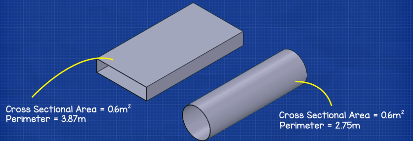
A round duct with a cantankerous sectional expanse of 0.6m2 has a perimeter of ii.75m
A rectangular duct with an equal cross sectional area has a perimeter of three.87m
The rectangular duct therefore requires more than metal for its structure, this adds more weight and costs to the design. The larger perimeter also means more air will come into contact wit the cloth and this adds friction to the system. Friction in a arrangement means the fan needs to work harder and this results in college operating costs. Always employ round duct where possible although in many cases rectangular duct needs to exist used as space is limited.
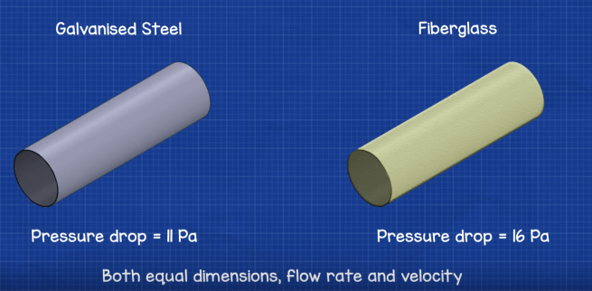
The second thing to consider is the material being used for the ducts, and the roughness of this material as this causes friction. For case, if we had two ducts, with equal dimensions, volume flow rate and velocity, the only difference is the material. One is made from standard galvanised steel the other from fibreglass, the force per unit area drop over a 10m distance for this instance, is effectually eleven Pa for the galvanised steel and sixteen Pa for the Fibreglass.
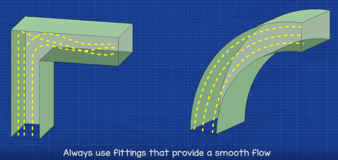
The third thing we accept to consider is the dynamic losses caused by the fittings. We want to use the smoothest fittings possible for energy efficiency. For example use long radius bends rather than right angles as the sudden change in direction wastes a huge amount of free energy.
We can compare the functioning of different ductwork designs, apace and easily using CFD or computational fluid dynamics. These simulations were produced using a revolutionary deject based CFD and FEA engineering platform, by SimScale, who have kindly sponsored this commodity.
You can access this software free of charge by clicking here, and they offering a number of dissimilar account types depending on your simulation needs.
SimScale is not just express to ductwork design, information technology'south as well used for information centers, AEC applications, electronics blueprint, also as thermal and structural analysis.
Only a quick look on their site and you can find thousands of simulations for everything from buildings, HVAC systems, estrus exchangers, pumps and valves to race cars and air planes, which can all be copied and used as templates for your own design analysis.
They as well offer free webinars, courses and tutorials to assist you prepare and run your own simulations. If similar me you have some experience creating CFD simulations so you lot'll know that this blazon of software is usually very expensive and you would also demand a powerful computer to run it.
With SimScale, yet, all tin can exist done from a web browser. As the platform is deject-based, their servers do all the piece of work and we tin access our design simulations from anywhere, which makes our lives as engineers a lot easier.
And so if you're an engineer, designer, builder or just someone interested in trying out simulation technology, and so I highly recommend you check this software out, get your free account by following this link.
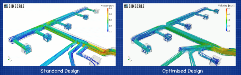
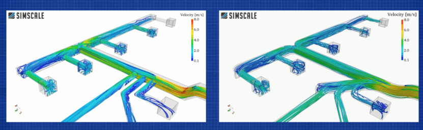
Now if we look at the comparing for the ii designs we have a standard design on the left and a more than efficient design on the right which has been optimised using simscale. Both designs use an air velocity of 5m/s, the colours correspond the velocity with blue meaning low velocity and red representing the high velocity regions.
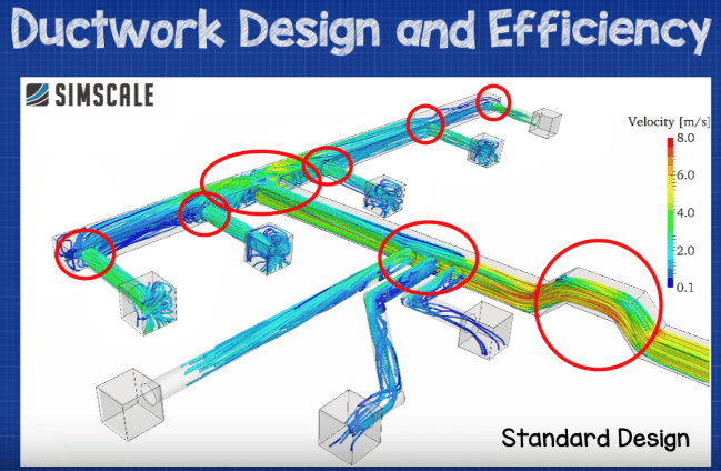
We can see from the velocity colour calibration and the streamlines that in the design on the left, the inlet air directly strikes the sharp turns that are present in the system which causes an increase in the static pressure level. The sharp turns cause a large amount of recirculation regions within the ducts, preventing the air from moving smoothly.
The tee department at the far finish of the principal duct causes the air to suddenly divide and change direction. There is a high amount of backflow here which again increases the static pressure and reduces the corporeality of air commitment
The high velocity in the chief duct which is caused past the sharp turns and sudden bends, reduces the period into the 3 branches on the left.
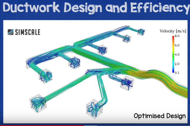
If nosotros now focus on the optimised design on the right, we run into the fittings used follow a much smoother profile with no sudden obstructions, recirculation or backflow which significantly improves the air menses rate inside the system. At the far end of the main duct the air is divided into two branches through a gentle, curved tee section. This allows the air to smoothly modify direction and thus at that place is no sudden increment in static pressure and the air flow rate to the rooms has dramatically increased.
The 3 branches within the main duct now receive equal air flow making a significant improvement to the design. This is because an additional co-operative now feeds the three smaller branches assuasive some of the air to smoothly break away from the main flow and feed into these smaller branches.
With these considerations in identify we tin can come up back to the duct design.
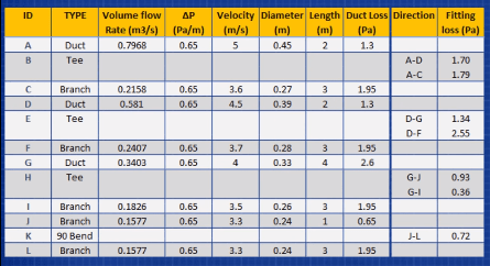
Now we need to label every section of ductwork as well as the fittings with a letter of the alphabet. Notice nosotros are but designing a very elementary system here so I've only included ducts and basic fittings, I've non included things such equally grilles, inlets, flexible connections, burn dampers etc.
Now we want to make a table with the rows labelled equally per the example. Each duct and fitting needs its own row, if the air stream splits such equally with a Tee section, and then we need to include a line for each management, we'll see that later in the commodity.
Just add in the letters to separate rows so declare what type of fitting or duct that corresponds to.
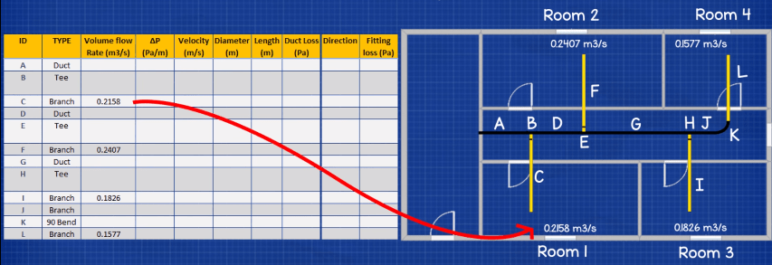
We can kickoff to fill some of the information in, we tin offset include the volume flow rates for each of the branches, this is easy equally its but the volume menstruum rate for the room which it serves. You tin can run across on the nautical chart I've filled that in.
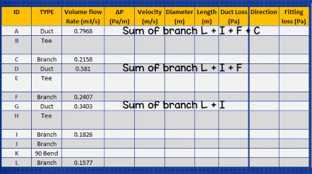
Then we tin can kickoff to size the main ducts. To do this make sure you beginning at the main duct which is furthest abroad. Then nosotros only add together up the volume period rates for all the branches downstream of this. For the main duct G we just sum branches L and I. For D that's just the sum of Fifty I and F and for duct A its and then the sum of Fifty, I, F and C. so just enter those into the table.
From the rough drawing we measure out the length of each duct section and enter this into the chart.
Duct sizing – How to size ductwork
To size the ducts you're going to demand a duct sizing chart. You tin can obtain these from ductwork manufacturers or from industry bodies such equally CIBSE and ASHRAE. If y'all don't have one, yous can detect them in the following links. Link 1 and Link two
These charts hold a lot of information. We can employ them to find the pressure drop per meter, the air velocity, the volume menstruum rate and also the size of the ductwork. The layout of the nautical chart does vary a little depending on the manufacturer but in this case the vertical lines are for pressure drop per meter of duct. The horizontal lines are for volume flow rate. The downwards diagonal lines are for velocity, the up diagonal lines are for duct bore.
We commencement sizing from the first main duct which is department A. To limit the noise in this section we'll specify that it can only have a maximum velocity of 5m/s. We know that this duct also requires a volume flow charge per unit of 0.79m3/southward so we can use the velocity and volume flow rate to find the missing data.
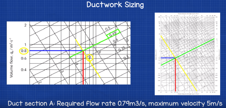
We have the chart and scroll up from the bottom left until nosotros hit the book flow charge per unit of 0.79m3/south. And then nosotros locate where the velocity line is of 5m/s and we draw a line across until we hitting that. So to detect the pressure drib nosotros draw a vertical line downward from this intersection. In this example we meet it comes out at 0.65 pa per meter. So add this figure into the chart. As we're using the equal force per unit area drop method we can use this pressure driblet for all the duct lengths and then fill those in besides. Then nosotros scroll upwardly once more and marshal our intersection with the up diagonal lines to see this requires a duct with a diameter of 0.45m so we add that into the table also.
Nosotros know the book period rate and pressure drop so nosotros can at present calculate the values for section C and then the remaining ducts.
For the remainder of the ducts nosotros use the same method.
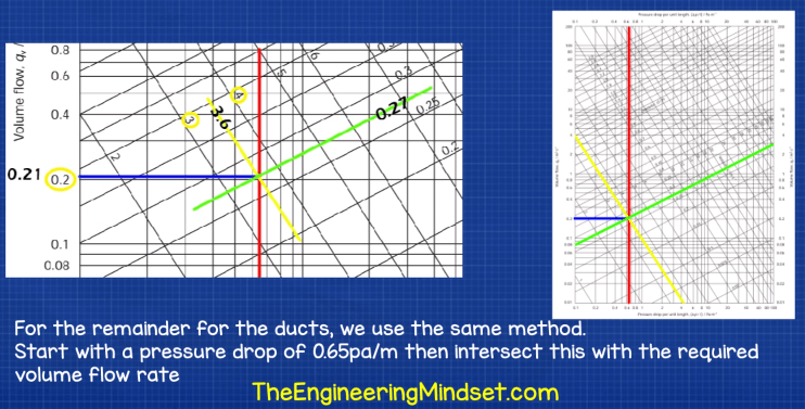
On the chart we start past cartoon a line from 0.65 pa/chiliad all the way upwardly and then draw a line across from our required volume flow charge per unit, in this example for section C we need 0.21m3/south. At this intersection we draw a line to detect the velocity and we can see that it falls inside the lines of iii and 4m/s so we need to approximate the value, in this instance it seems to be virtually 3.6m/s so we add that to the chart. Then we draw another line on the other diagonal grid to find our duct diameter which in this case is about 0.27m and nosotros'll add that to the table too.
Repeat that final process for all the remaining ducts and branches until the table is complete.
Now detect the full duct losses for each duct and branch, that's very easy to do just multiply the duct length by the force per unit area drop per meter, in our instance we institute information technology to be 0.65pa/m. Exercise that for all the ducts and branches on the table.
Sizing ductwork fittings
The outset fitting we'll look at is the 90* curve between ducts J and L
For this we expect up our loss coefficient for the curve from the manufacturer or the industry body, y'all tin can notice that by clicking this link.
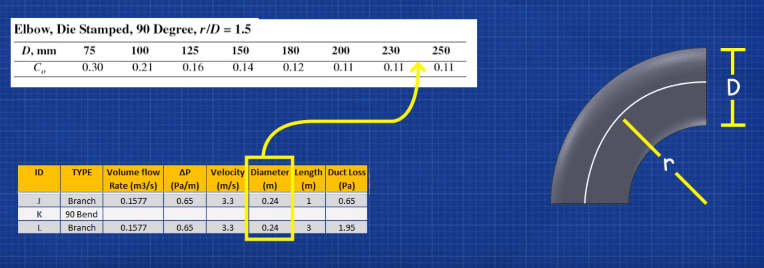
In this example we can see the coefficient comes out at 0.11
We then need to calculate the dynamic loss acquired by the curve changing the management of flow. For that we utilise the formula Co multiplied by rho multiplied by five squared divided by 2 where co is our coefficient, rho is the density of the air and v is the velocity.
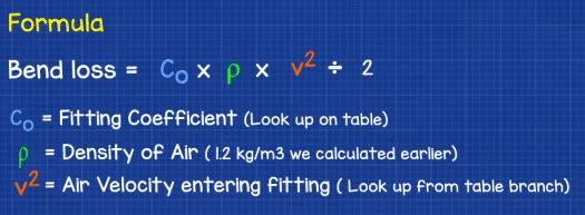
We already know all these values so if nosotros drop the figures in we go an answer of 0.718 pascals. Then merely add that to the table. (Watch the video at the bottom of the page to run across how to summate that).
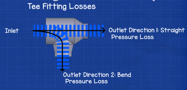
The side by side plumbing equipment we'll look at is the tee which connects the main duct to the branches, we'll employ the case of the tee with the ID letter H between G and J in the arrangement. Now for this we need to consider that the air is moving in ii directions, straight through and also turning off into the branch so we need to perform a adding for both directions.
If we look at the air travelling straight though outset, we find the velocity ratio first using the formula velocity out divided by velocity in. In this example the air out is three.3m/south and the air in is 4m/s which gives us 0.83
And so we perform another calculation to find the expanse ratio, this uses the formula bore out squared divided by diameter in squared. In this example the diameter out is 0.24m and the diameter in is 0.33m so if nosotros square them and then divide we get 0.53
Now nosotros look up the fitting nosotros're using from the manufacturer or the industry body, again link here for that.
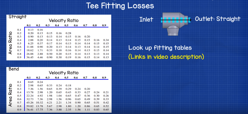
In the guides we detect two tables the i you utilize depends on the direction of flow, we're using the directly direction so we locate that one and and so wait upward each ratio to find our loss coefficient. Here yous can come across both of the values we calculated fall betwixt vales listed in the table so we need to perform a bilinear interpolation. To save time we'll just apply an online calculator to detect that, link hither (sentry the video to learn how to perform a bilinear interpolation).
Nosotros make full out our values and nosotros find the respond of 0.143
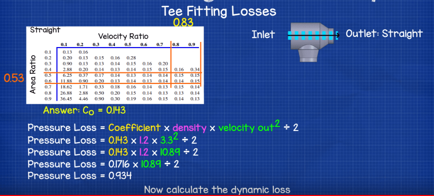
Now we calculate the dynamic loss for the direct path through the tee, using the formula co multiplied past rho multiplied by v squared divided past 2. If nosotros driblet our values in we go the answer of 0.934 pascals so add that to the table.
So we can summate the dynamic loss for the air which turns into the bend. For this nosotros use the same formulas as before. Velocity out didived past velocity in to find our velocity ratio. Then nosotros discover the area ratio using the formula diameter out squared divided past diameter in squared. Nosotros take our values from our table and utilise 3.5m/south divided by 4m/south to get 0.875 for the velocity ratio and we utilize 0.26m squared divided by 0.33m squared to get 0.62 for the surface area ratio.
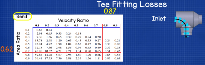
Then we utilize the bend table for the tee department, once more its betwixt the values listed in the table so we have to detect the numbers using bilinear interpolation. Nosotros driblet the values in to go the answer of 0.3645 pascales. So just add that to the table too.
Now echo that calculation for the other tees and fittings until the table to complete.
 Finding the index run – duct sizing
Next we demand to detect the index run which is the run with the largest pressure driblet. Information technology's usually the longest run but could too exist the run with the most fittings.
We notice it easily by adding upward all the force per unit area losses from the offset to the exit of each co-operative .
For example to go from A to C we lose 5.04pa
A (ane.3pa) + B (one.79pa) + C (1.95pa)
For A to F nosotros lose viii.8pa
A (i.3pa) + B (1.7pa) + D (one.3pa) + E (2.55pa) + F (i.95)
For A to I nosotros lose 10.56
A (one.3pa) + B (1.7pa) + D (1.3pa) + E (ane.34pa) + G (2.6pa) + H (0.36pa) + I (1.95pa)
For A to Fifty we lose 12.5pa
A(1.3pa) + B (ane.7pa) + D (1.3pa) + East (1.34pa) + Yard (2.6pa) + H (0.93pa) + J (0.65pa) + Yard (0.72pa) + L (ane.95pa)
Therefore the fan we use must overcome the run with the highest loss, that being A – L with 12.5pa, this is the alphabetize run.
Ductwork dampers – system balancing
To residuum the arrangement we need to add dampers to each of the branches to ensure equal pressure drop through all to achieve the design flow rates to each room.
We can calculate how much force per unit area drop each damper needs to provide simply by subtracting the loss of the run from the index run.
A to C is 12.5pa – v.04pa = vii.46pa
A to F is 12.5pa – 8.8pa = three.7pa
A to I is 12.5pa – 10.56pa = i.94pa
And that is our ducting system. We'll do some other tutorial covering boosted ways to improve efficiency in ductwork arrangement.

How Can We Calculate The Duct Size,
Source: https://theengineeringmindset.com/ductwork-sizing-calculation-and-design-for-efficiency/
Posted by: holmbergknome1944.blogspot.com
0 Response to "How Can We Calculate The Duct Size"
Post a Comment